Search This Blog

Monday, September 14, 2026

When Should Engineers Use a Conduction Cooled Capacitor?

Suntan TS24 Conduction Cooled Capacitors for High-Power Resonant Circuits

SUNTAN TECHNOLOGY COMPANY LIMITED · HIGH-POWER FILM CAPACITOR SPECIALIST
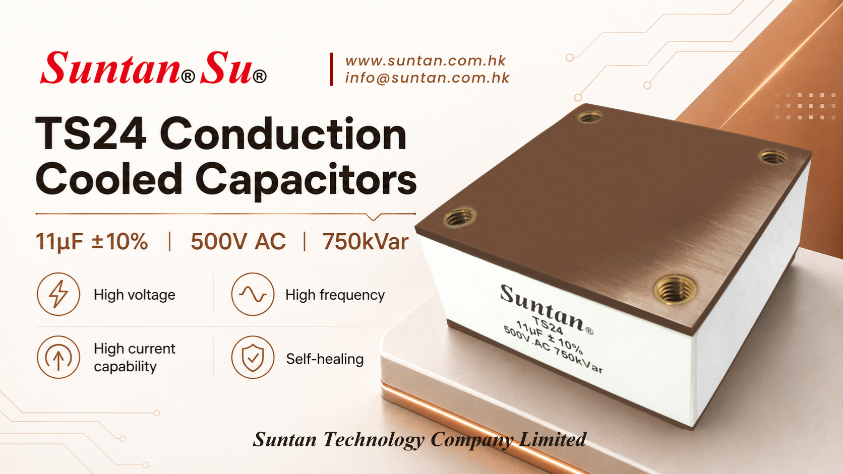
Suntan TS24 Conduction Cooled Capacitor for High-Power Resonant Systems Figure 1: Suntan® TS24 conduction cooled capacitor designed with robust mounting surfaces for direct thermal management on liquid-cooled cold plates.

High-Power Thermal Management with Conduction Cooled Capacitors: Suntan TS24 Engineering Guide

In next-generation medium- and high-frequency power electronics, thermal dissipation is frequently the definitive bottleneck constraining system miniaturization and power density. As switching frequencies rise into the tens and hundreds of kilohertz and circulating currents surge past several hundred amperes, conventional convective airflow cooling methods rapidly reach their physical limits.

As an experienced conduction cooled capacitor manufacturer, Suntan Technology Company Limited® engineered the TS24 Series specifically for high-power, high-frequency resonant circuits. By conducting internally generated thermal energy directly into mounting surfaces, busbars, and liquid-cooled cold plates, the TS24 delivers ultra-low thermal resistance, high dv/dt endurance, and exceptional reactive power handling (up to 800 kVar) within a remarkably compact structural envelope.

Why Conduction Cooling Outperforms Air Cooling in High-Power Systems

Operating high-power film capacitors inside compact, dust-tight, or liquid-sealed enclosures (such as IP65/IP67 cabinets) imposes severe thermal management challenges:

  • Direct Solid-State Thermal Path: Instead of relying on low-efficiency air convection, the TS24 establishes an ultra-low thermal resistance (Rth) interface by bolting directly onto chassis heatsinks or water-cooled copper cold plates.
  • Internal Hotspot Prevention: Massive circulating tank currents generate heavy Joule heating. Direct conduction extracts heat immediately from the low-loss dielectric winding, preventing localized hotspot accumulation and thermal runaway.
  • Compact Enclosure Compatibility: Ideal for space-constrained power converters where forced air fans cannot be deployed due to acoustic noise, contamination risks, or hermetic sealing requirements.
  • Extended Operational Reliability: Under rigorously controlled hotspot temperatures, the TS24 maintains stable capacitance values and delivers an operational service life of up to 200,000 hours at rated conditions.

Suntan® TS24 Series Technical Specifications Matrix

The table below outlines the core operating ratings, dielectric characteristics, and technical documentation references for the Suntan TS24 series:

Series Platform Dielectric & Cooling Structure Key Electrical Ratings Reactive Power Documentation
TS24 Series Low-Loss Polypropylene Film / Direct Conduction Plate & Busbar Mount Rated Voltage: 400 VAC – 1,000 VAC
Capacitance: 0.1 μF – 84 μF
tan δ ≤ 5 × 10⁻⁴ (1 kHz)
300 kVar, 600 kVar, 750 kVar, 800 kVar TS24 Page & PDF →

Key Industrial Applications for Conduction Cooled Capacitors

The TS24 series is engineered to excel in demanding industrial environments requiring continuous high-power throughput and extreme frequency stability:

  • Induction Heating & Melting Furnaces: Functions as the primary resonant tank capacitor, carrying hundreds of amperes across LC tank circuits while securely bolted onto water-cooled copper cold plates.
  • High-Frequency Resonant Inverters & Converters: Supplies reactive compensation and energy storage in LLC, LCC, and full-bridge zero-voltage switching (ZVS) power architectures.
  • High-Power Industrial Welding Equipment: Withstands heavy pulse loads, repetitive high-current discharges, and rapid switching transients with elevated dv/dt rates.
  • EV High-Power Wireless Power Transfer (WPT): Enables primary and secondary magnetic resonant coupling with a high quality factor (Q) and minimal transmission loss.

Engineering Selection Checklist for High-Power Film Capacitors

When sizing a conduction cooled capacitor for your system design, hardware engineers should systematically verify the following technical parameters:

  • 1. Working AC/DC Voltage: Calculate continuous RMS voltage, peak working voltage, and appropriate safety margins against harmonic-induced overvoltages.
  • 2. Continuous RMS Current (IRMS): Compare maximum circulating currents against current-versus-frequency de-rating curves to prevent thermal overload.
  • 3. dv/dt Withstand Capability: Ensure the capacitor's rated dv/dt tolerance (V/μs) accommodates switching rise times (Ipeak = C × dv/dt).
  • 4. Operating Frequency: Match the resonant tank frequency with the dielectric dissipation factor (tan δ) to minimize high-frequency ESR losses.
  • 5. Thermal Path & Heatsink Interface: Verify mounting interface flatness (≤0.05 mm), apply a thin thermal interface material (TIM), and adhere strictly to specified busbar torque limits.
  • 6. Rated Reactive Power (kVar): Confirm required kVar capacity under full-load continuous duty cycles.

Frequently Asked Questions — Conduction Cooled Capacitor Engineering FAQ

What is a conduction cooled capacitor?

A conduction cooled capacitor is a specialized high-power, high-frequency capacitor designed to transfer internally generated thermal energy away via direct solid-state contact with an external heatsink, cold plate, or heavy-duty busbar mounting surface, rather than relying on natural or forced-air convective airflow. This solid-state thermal path provides superior thermal conductivity and allows components to withstand hundreds of kilovolt-amperes reactive (kVar) within compact footprints.

Explore TS24 Conduction Cooled Design →
When should I use a conduction cooled capacitor?

Engineers should specify conduction cooled capacitors when power conversion circuits handle extreme continuous RMS currents (hundreds of amperes), high operating frequencies (tens to hundreds of kHz), compact sealed enclosures (such as IP65/IP67 equipment), or operating environments where restricted airflow prevents conventional air cooling from preventing thermal runaway.

Why is conduction cooling better for high-power capacitors?

Conduction cooling creates a direct metallic thermal pathway with minimal thermal resistance (Rth) between the internal film winding and the cooling plate. By conducting heat efficiently through the mounting surface, internal hotspot temperatures are kept low, stabilizing capacitance, suppressing dielectric degradation, and ensuring dependable operational stability under continuous full-load excitation.

What is dv/dt in a film capacitor?

dv/dt defines the maximum permissible rate of voltage change across the capacitor over time (measured in V/μs). In high-frequency resonant circuits and fast-switching inverter bridges, rapid commutations create severe dv/dt transients. High dv/dt capability ensures that the capacitor withstands repetitive peak currents (Ipeak = C × dv/dt) without dielectric punch-through or terminal metallization failure.

Why is low ESR important in high-power capacitors?

Equivalent Series Resistance (ESR) reflects the internal ohmic losses within the dielectric film and metallized terminations. Because power dissipation scales with the square of the RMS current (Ploss = IRMS2 × ESR), ultra-low ESR is critical to suppressing self-heating, preserving electrical efficiency, and preventing destructive thermal breakdown.

Review Low-ESR TS24 Technical Specs →
Are conduction cooled capacitors used in induction heating?

Yes. Conduction cooled capacitors are fundamental components in induction heating generators and melting systems. Connected in series or parallel with induction coils to form the resonant LC tank, they manage continuous reactive power (300 kVar to over 800 kVar) and hundreds of amperes of circulating current while securely mounted onto liquid-cooled cold plates.

Can conduction cooled capacitors be used in resonant circuits?

Absolutely. Capacitors such as the Suntan TS24 are purpose-engineered for series and parallel resonant converters (including LLC, LCC, and tank configurations). Their tight capacitance tolerance, high quality factor (Q), low dissipation factor (tan δ), and extreme current capacity ensure precise resonant tuning and negligible loss under high-frequency operation.

What applications use conduction cooled capacitors?

Key applications encompass induction heating and melting furnaces, high-frequency resonant power supplies, industrial welding systems, high-power wireless EV charging platforms (WPT), plasma power generators, and medical RF power equipment.

How do I select a conduction cooled capacitor?

Follow a structured selection workflow: 1) Verify operating AC/DC continuous voltage; 2) Determine maximum continuous RMS current and switching frequency; 3) Confirm peak dv/dt withstand capability; 4) Calculate required reactive power (kVar); 5) Inspect mounting interface flatness, thermal interface material (TIM), and correct busbar connection torque.

How long do conduction cooled capacitors last?

When operated strictly within designated electrical ratings and hotspot temperature limits—supported by proper cold-plate or heatsink thermal management—Suntan TS24 conduction cooled capacitors can achieve an expected service life of up to 200,000 hours at rated conditions. Exceeding rated hotspot temperatures accelerates dielectric aging and proportionally shortens service life.

Suntan® supports power electronics designers, induction heating equipment builders, and resonant converter manufacturers worldwide. For cross-referencing, custom terminal mountings, or sample requests, please contact our technical sales team.
Wednesday, September 2, 2026

Varistors for AI Data Center Power: Surge Protection from PSU to UPS

SUNTAN TECHNOLOGY COMPANY LIMITED · VARISTORS & OVERVOLTAGE CIRCUIT PROTECTION SPECIALIST

Suntan TSV TSVG Metal Oxide Varistors and TSVC Multilayer Chip Varistors for Emerging Power Electronics
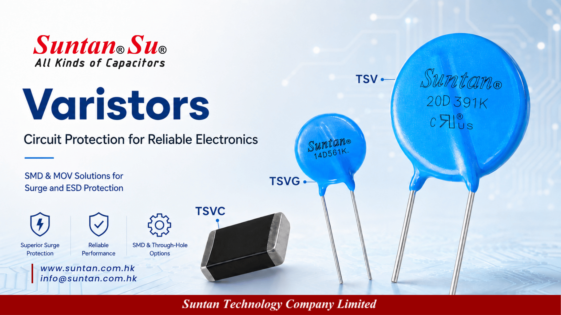
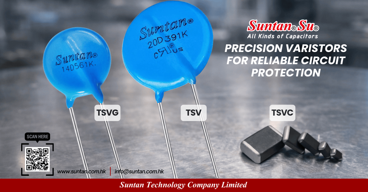
Figure 1: Comprehensive Suntan® varistor lineup covering radial disc MOVs (TSV / TSVG) and SMD multilayer chip varistors (TSVC).

Varistors for AI Data Center Power: Surge Protection from PSU to UPS

Rapid advancements in high-power computational hardware, electric mobility, renewable storage, and industrial automation have introduced unprecedented electrical transient stress. In modern architectures—such as high-density AI data center power distribution units (PDUs), commercial EV DC fast chargers, photovoltaic energy storage systems (ESS), and agile robotic servo drives—power lines face severe lightning-induced surges, continuous switching ringing, and inductive kickbacks.

Suntan Technology Company Limited® offers an extensive portfolio of overvoltage suppression solutions: the standard TSV Zinc Oxide Varistor, the upgraded high-temperature/high-surge TSVG Series, and the ultra-compact TSVC Multilayer Chip Varistor (SMD). Designed to comply with global safety benchmarks (including UL 1449, VDE, and IEC 61000-4-5), Suntan varistors provide dependable clamping protection to ensure continuous equipment uptime.


Critical Protection Roles in Emerging Power Electronics Sectors

Selecting the appropriate varistor technology depends directly on the localized surge severity and operational environment:

  • AI Data Centers & Server Power Shelves: Dynamic load steps across GPU server clusters generate high-frequency switching noise and grid-level spikes. Robust radial MOVs safeguard primary AC-DC rectifiers, while low-capacitance SMD varistors clamp secondary telemetry and communication lines.
  • EV Fast Charging Infrastructure: Outdoor EV chargers operate in harsh outdoor environments vulnerable to lightning strikes and DC bus inductive transients during vehicle connection cycles, requiring high-energy 14D and 20D varistors.
  • Solar Inverters & ESS: Rapid DC-to-AC conversion and battery rack relay switching produce continuous inductive back-EMF, demanding varistors with superior thermal stability to avoid thermal runaway.
  • Robotics & Motion Control: Servo drive electronics and dynamic motor braking generate transient energy spikes that must be safely clamped right at motor drive terminal interfaces.

Suntan® Varistor Series Comparison & Technical Matrix

Compare technical parameters, form factors, and target applications across Suntan's primary varistor platforms:

Series Platform Form Factor & Structure Key Operating Specifications Primary Application Focus Datasheet Resource
TSV Series Radial Lead Disc MOV (5D, 7D, 10D, 14D, 20D) Varistor Voltage: 18V – 1800V; 8/20 μs Peak Surge: up to 6,500A (20D); Temp: -40°C to +85°C Mains AC input filtering, industrial SMPS, home appliances, power adapters Download TSV PDF
TSVG Series High Temp & High Surge Disc MOV (5D to 20D) Upgraded Temp: -40°C to +105°C; Enhanced surge current handling & superior Joule energy absorption AI data center power shelves, outdoor EV charging posts, solar PV combiners, industrial robotics Download TSVG PDF
TSVC Series Multilayer SMD Chip Varistor (0402, 0603, 0805, 1206, 1210) Working Voltage: 3.3V – 68V; Response Time: <0.5ns; Low capacitance (<4pF for USB 2.0); Bi-directional ESD High-speed communication ports (USB/Ethernet/CAN), microcontroller I/O, sensors, smart metering Download TSVC PDF

MOV Disc Diameter Sizing Guide (7D, 10D, 14D, 20D)

The physical disc diameter directly determines an MOV's peak surge current capability (8/20 μs waveform) and total energy absorption (measured in Joules for a 2ms pulse). Selecting the correct size balances protection margin against PCB real estate:

Disc Diameter Peak Surge Current (8/20 μs, 1 Time) Energy Absorption Capability (2ms) Recommended Application Context
7D (7mm) 1,200A – 1,750A Approx. 9J – 30J Compact auxiliary power supplies, LED drivers, smart meters, IoT devices
10D (10mm) 2,500A – 3,500A Approx. 25J – 70J Standard desktop power adapters, consumer appliances, white goods
14D (14mm) 4,500A – 6,000A Approx. 50J – 150J Industrial SMPS, telecom rectifiers, solar microinverters (e.g., 14D471K)
20D (20mm) 6,500A – 10,000A Approx. 130J – 360J Heavy industrial motor drives, EV charging stations, building service entrance (e.g., 20D391K)

Technical Demonstration Video: MOV & SMD Varistor Manufacturing

Review our structured video overview showing MOV disc construction, taping specifications, and multilayer chip varistor packaging:


People Also Ask: Varistor Selection & Engineering FAQ

Component Sizing · 7D to 20D

What size MOV should I use?

MOV disc diameter (7D, 10D, 14D, 20D) dictates peak surge current handling (8/20 μs) and energy absorption (Joules). For compact adapters and small auxiliary circuits, 7D or 10D is standard. For industrial power equipment, outdoor EV charging stations, and AI server power shelves, 14D and 20D models are strongly recommended to endure heavy transient strikes without degradation.

Voltage Calculation · V1mA & Vc

How do I choose a varistor voltage?

Follow a three-step selection procedure: 1) Identify the continuous operating voltage (VRMS for AC or VDC for DC) and add a 15% to 25% safety headroom to prevent premature conduction during normal line fluctuations; 2) Choose a nominal Varistor Voltage (V1mA) matching that threshold; 3) Verify that the maximum Clamping Voltage (VC) at expected peak surge currents remains below the maximum breakdown rating of downstream components.

Design Trade-Offs · Surge vs Space

Is a bigger MOV always better?

A larger MOV disc (e.g., 20D vs. 10D) provides higher surge current capacity, lower thermal stress, and longer operating life under repetitive surges. However, trade-offs include higher component cost, larger PCB footprint, greater height, and increased parasitic capacitance. Hardware designers must balance required surge robustness against physical layout constraints.

Technology Comparison · MOV vs SMD

What is the difference between an MOV and an SMD varistor?

Radial leaded disc MOVs (Suntan TSV and TSVG) are designed primarily for primary AC and DC power lines to absorb high-energy, high-current surges (in the kilo-ampere range). In contrast, SMD multilayer chip varistors (Suntan TSVC) protect low-voltage secondary circuits and high-speed data interfaces (USB, Ethernet, CAN) against fast-rising electrostatic discharge (ESD) and low-energy transients with sub-nanosecond response times.

Mains Selection · 230V AC Input

What varistor is used for 230V AC mains?

For standard 230V AC utility grids, voltage fluctuations can reach 265V AC or higher. Therefore, the varistor's continuous maximum AC voltage (VRMS) must be at least 275V to 300V. Common industry choices include nominal 430V or 470V varistor voltage models (such as 14D431K or 14D471K), depending on localized surge test specifications.

Part Number Decoding · 14D471K

What does 14D471K mean?

This standard part number code designates:
• 14D: 14mm disc diameter body size;
• 471: Nominal varistor voltage of 47 × 101 = 470V (measured at 1mA DC);
• K: Voltage tolerance of ±10%.

Part Number Decoding · 20D391K

What does 20D391K mean?

This part number designates a heavy-duty surge varistor:
• 20D: 20mm disc diameter capable of handling up to 6,500A peak surge current;
• 391: Nominal varistor voltage of 39 × 101 = 390V at 1mA;
• K: Tolerance of ±10%. Frequently selected for 220V/240V AC power systems requiring a tight clamping threshold.

Pulse Endurance · 8/20 μs Current

How much surge current can an MOV handle?

Surge handling is evaluated using standard 8/20 μs current pulses. Standard 7D discs manage up to 1,200A; 10D discs handle 2,500A; 14D discs handle 4,500A; and 20D discs handle 6,500A or higher. Upgraded TSVG high-surge series provide enhanced pulse endurance and elevated thermal endurance up to +105°C.

ESD Protection · High-Speed Signal Lines

Can varistors protect against ESD?

Yes, but selection of the correct construction is critical. While radial MOVs are too slow and excessively capacitive for high-speed data lines, Suntan TSVC Multilayer Chip Varistors are specifically engineered for IEC 61000-4-2 ESD protection, featuring sub-nanosecond response times (<0.5ns) and low parasitic capacitance.

Interface Integrity · USB & High-Speed Data

What capacitance should ESD protection have for USB interfaces?

For high-speed communication interfaces like USB 2.0, excessive parasitic capacitance causes severe signal degradation and eye-diagram distortion. According to the Suntan TSVC engineering datasheet, varistor capacitance should be selected below 4pF (with ultra-low capacitance options <1pF recommended for ultra-high-speed differential pairs).

PCB Layout Rules · Placement & Traces

Where should a varistor be placed on a PCB?

A varistor must be positioned as close as possible to the power input connector or entry port, directly downstream of the primary fuse or thermal cutoff. PCB traces connecting to the varistor must be short and wide to minimize parasitic trace inductance, ensuring transient spikes are clamped before propagating into sensitive downstream circuits.

Reliability & Safety · Aging Mechanism

How do I know when an MOV needs replacement?

MOVs experience gradual degradation after absorbing repetitive transient energy pulses. Symptoms of aging include increased leakage current, decreased nominal breakdown voltage (V1mA), and elevated steady-state operating temperature. In severe overstress conditions, visible discoloration or body cracking occurs. Incorporating a series thermal disconnect (TMOV configuration) helps prevent catastrophic short-circuit failures at end of life.


Explore Suntan® Varistor Portfolio Today

Figure 2: Quality-inspected Suntan® metal oxide varistors packaged for global delivery.

Suntan Technology Company Limited · High-Reliability Electronic Components Since 1978.
Providing robust zinc oxide varistors, multilayer chip suppressors, capacitors, and trimming potentiometers for global clients.